ATF15xx VHDL Development on the Cheap
Contents
CPLDs are super useful tools for the hobbyist as well as professionals - they save you the bother of trying to assemble logic circuits out of hard-to-find 7400-series logic chips, make it much easier to lay out your circuit boards (with most of the complex layout being effectively ‘inside’ the chip, and programmed by burning fuses with a programmer,) and maybe best of all let you reconfigure that logic (either by design or because of a mistake) without needing to rewire your circuit or redesign your board. What’s not to like?
They are also, if you are using something like the Atmel ATF15xx series, ridiculously cheap. One chip costing less than two euros can replace dozens of logic chips.
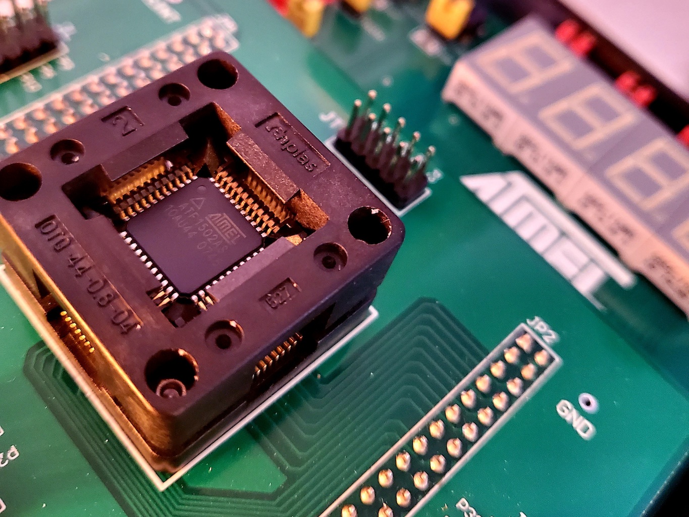
Apart from being cheap, the ATF15xx series have another strong selling point - they come in hobbyist-friendly TQFP-44 packages that are - for surface-mount devices - relatively easy to hand solder.
So, in short, I like the hardware. The software situation though is not quite so pretty…
If you’re already familiar with the CPLD development toolchain, you can skip ahead to the interesting part about how to find working tools for Atmel, otherwise I’ll take a short digression on what you need. (Or you can skip even further ahead if you really really just want the facts, ma’m.)
Software development for CPLDs⌗
To develop the logic that you will program into these things, first you need to write the specification for how the logic gates will be connected. This can be as simple as some kind of schematic-capture tool where you literally draw the logic gates and the connections between them, but in general you will want to use an HDL - a Hardware Description Language. This is effectively a programming language, but instead of describing processes, as in a traditional language, you are describing circuits - that is, how logic is connected together. You can think of it as being like a programming language where instead of things being executed serially, all the logic is constantly running in parallel.
To take a really simple example, this is how I could defined a simple AND gate using the VHDL language:
ENTITY MyComponent IS
  PORT (
    A   : in std_logic;
    B   : in std_logic;
    out : out std_logic
  );
END MyComponent;

ARCHITECTURE behaviour OF MyComponent IS
BEGIN
  out ← A AND B;
END behaviour;
Here we’re saying that MyPieceOfLogic has two inputs, A and B, which are
standard logic (wires, basically) that can be 1 (on) or 0 (off), and also one
output. Then we say that the behaviour of that is defined by the logical
function out ← A AND B.
Sidenote: On HDL Languages⌗
Now, much as with regular programming there are several different HDL languages, each with their pros and cons. The two most well known are probably VHDL and Verilog. But there are others - once upon a time there was a purely functional HDL called Ruby, although finding information about it is now tricky since some upstart web development language stole the same name.
Now, I am not qualified to say which is the ‘best’ HDL to use… But I was taught VHDL1 at university 25 years ago, and when I discovered it I literally thought this is the most amazing magic I have ever seen. So, when I now came to playing with CPLDs in later life, naturally it was the language I wanted to pick up again.
The development lifecycle⌗
So, once you have your programming language settled, just as with developing in any other language you need a ’toolchain’ to actually build your software and get it onto the hardware. In regular languages you need a compiler, and then possibly a second-stage compiler or assembler, and a linker to stitch everything together, and then finally some way of loading the code into your device.
The rough equivalent workflow for an HDL and CPLD is as follows:
- Modelling; that is, describing your application in the HDL. For this you need a text editor :).
- Analysing: this is where you compile your HDL, i.e. confirm that your code is syntactically correct.
- Simulation: this is where you check that your code is semantically correct - i.e. does it actually do what you wanted it to. This is done with a ’testbench’ of possible inputs, and then the simulation confirms that the outputs of your program match the outputs you would expect for those inputs.
- Synthesising: This is where you compile your HDL into the actual series of logic gates and components that is needed to actually represent your logic in hardware. The output of this stage is effectively a netlist - a list of logic components and the connections between them.
- Fitting: This is where the netlist from the synthesiser is mapped onto the actual capabilities of the chip you are trying to program. It will work out which fuses need to be programmed in the chip to re-create the logic circuit you described in the HDL. At this point, you also want to tell the fitter which of the inputs/outputs (ports) in your circuit map to the real physical pins on your chip (and, to which one - or you can let the fitter work that out for itself and then have it tell you that, for example, port A in MyComponent will be pin 32 on the actual chip.2)
- Programming: Finally, you upload your design to the chip using a programmer.
So, this is the toolchain we want to find for our ATF15xx CPLDs. Unfortunately,
it’s not quite as easy as just installing everything from a handy
repository. There is no equivalent to brew install vhdl-atmel in this world
yet.3
Atmel Development Tools⌗
I’ve mentioned the Microchip ATF15XX-DK3 before - it’s a super nice evaluation and testing board for the ATF15xx CPLDs, complete with a programmer that you can hook up to your computer with USB and use it to program the chips either within the ATF15xx itself, or once they’re on your own circuit using a standard JTAG interface. You can buy it direct from Microchip, and it basically means for the hardware side of things we’re golden.
The software side though is slightly more problematic. To their credit, Atmel do offer an entirely free development environment that uses the CUPL hardware description language - it’s called WinCUPL and you can download it here.
If you’re entirely new to CPLDs and aren’t particularly bothered about which language you use, I’ve no reason to believe WinCUPL isn’t a good choice - so you can stop reading now and just head over there to start playing. But as noted above - I learned VHDL a long time ago, and so that’s the language I want to use. And that’s a problem…
You want VHDL? You must have money!⌗
Fundamentally, the problem is that the general perception seems to be - if you are doing VHDL development you must be a ‘professional’, and that means you must have 5-figure dollars to spend just on the software tools. As I said somewhere else - developing for hardware is like stepping back in time 30 years compared to software development, and in this world the equivalent of ‘compilers’ and ‘development kits’ are still expected to be expensive treasures that are hidden from the hoi-polloi.
Now, I don’t entirely blame Atmel/Microchip for this. They do have VHDL development tools for these chips - ProChip Designer - and while it is licensed software, in my limited communications with them they actually seem very nice and hobbyist friendly.
The problem is, almost all of these tools depend on one company, Mentor Graphics, to provide the simulation and synthesis components. And Mentor come straight out of the golden-age of price gouging license fees and “we’re too important for you” software development. So, unless we can find a way round it, we’ve reached a dead end…
As an aside, I don’t just object to Mentor because of the “if you have to ask, you can’t afford it” pricing model. I’m actually not at all against paying for high quality software - I happily hand over my money to Autodesk for Fusion and Eagle not because I’m a professional 3D designer (I’m not,) but because I believe in paying a fair price for high quality software.
I object to Mentor’s licensing more in part because it’s not high quality software (it’s not just the licensing models that are stuck 30 years in the past), but also because they use the horrendously regressive FLEXlm license management system that allows them to have ridiculous licensing models like “can only be installed on one physical machine” and “if you want to access that machine over remote desktop, you have to pay more” (because of course, in a world of Covid where everyone is working from home, naturally Mentor should get paid more if you want to remote-desktop into a work computer…)
The workaround⌗
Anyway, long story short (too late, I know,) there is a way round it. And I’m here to tell you what it is.
The ATF15xx is basically a really cheap Max7000⌗
The Max7000 family is a series of CPLDs developed by Altera (now Intel), a long time ago… They are no longer current, but once upon a time they were the hot new thing - and back in those days, Intel provided free development tools for them. Including VHDL, including a free edition of Mentor Graphics VHDL synthesiser, which doesn’t have an FLEXlm crap attached to it that stops you running it over remote desktop4.
The fantastic news is - that old version of the Intel software (Quartus II) is still available for download from Intel.
OK, so that’s great, we can now synthesise and fit our VHDL for the Max7000 devices, that’s not much use if I have an ATF1502 from Atmel… Except: In a stroke of luck (or, almost as if by design 🤔), Atmel provide a tool that will convert the fusemap for a Max7000 (known as a POF file) into the format (JEDEC) that their programmer expects!
So, we can use the Intel tools to develop our VHDL for a Max7000 - and then use Atmel’s tools to convert them into something we can load onto an Atmel ATF15xx part instead.
And guess what? It actually works!
Cutting a long story even shorter⌗
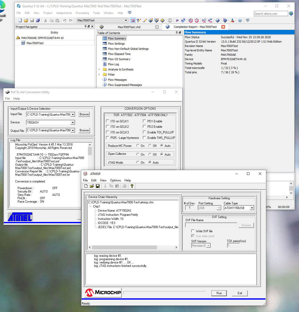
There was a lot of trial end error involved in this, but I’ve been through it all so you don’t have to. The final toolchain you need to be able to develop in VHDL for Atmel ATF15xx parts is as follows:
| Component | Link | Notes |
|---|---|---|
| Operating System | Windows | I’m sorry, right now there’s no way round this. Intel’s Quartus is available on Linux, but the Atmel tools aren’t so you’re going to need Windows anyway (for that reason, I’ve not tried Quartus on Linux, so can’t confirm if it works. But, I can confirm that this toolchain works on Windows 10, and also works running on a VM/over RDP. (You may need to disable UAC to get some of this wretched software to install properly though.) |
| Analysis/Synthesis/Fitting | Quartus v13.0.1 SP1 | This is not the latest version, but it is the last version with support for the Max7000 CPLDs, so it is the version you need. |
| Conversion to Atmel | POF2JED | You will use this to convert the POF files generated by Quartus into the JED files you can upload to your Atmel programmer |
| Programming | ATMISP | To take the output from POF2JED, and program it into your Atmel chip |
And that, pretty much, is that.
Good luck!
-
I was also taught Ruby, but as I’ve never been a fan of functional programming languages generally, the less said about that the better. ↩︎
-
Having the fitter work things out for itself will give you the most efficient use of the gates in your chip. The downside is that the pin allocation could change every time you change your design. This is fine if you plan to complete and finish your PLD design before you lay out the circuit board your chip is going on, but obviously not if you’ve already layed out a board where port A of MyComponent absolutely, definitely, needs to be on pin 31… ↩︎
-
Indeed, venturing into the world of electronics and hardware design is like stepping back in time 30 years compared to the way software development tools have evolved. It’s a miracle we are able to develop anything at all… ↩︎
-
Why am I so hung up about Remote Desktop? Well, like any right thinking developer, I don’t have a Windows desktop machine. I can just about bear to run Windows in a VM, and that’s exactly what I do - but that means typically I Remote Desktop onto that VM even if the machine it’s running on is sitting under my desk. ↩︎